
CONFIGURABLE PLATFORM / Robotics & Autonomous Battery Systems
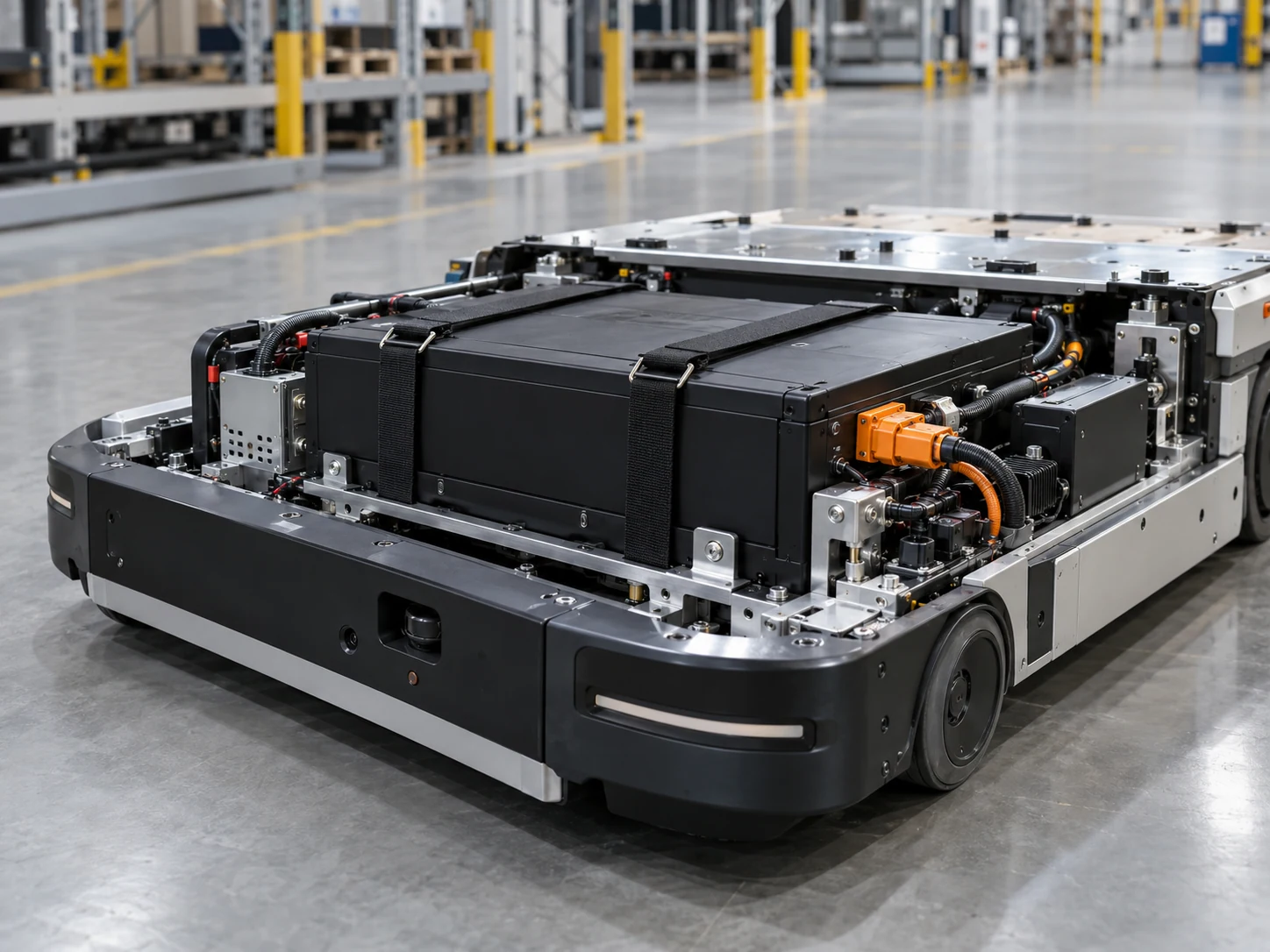
Robotics / Autonomous Battery Platform
A system-integration starting point for mobile robots and autonomous equipment.
- Machine fit
- Runtime profile
- Host interface
- Charging workflow
APPLICATION FIT
Where this platform fits
Frame the battery around the machine's operating cycle, changing loads and control requirements. Review traction and auxiliary demand, charging access and serviceability as one system brief.
Final suitability depends on your product requirements and the agreed validation plan.
- Mobile robotics
A robot that combines motion, computing and task loads within a constrained chassis.
Bring to the discussion: Operating cycle, overlapping loads and host-control requirements.
- Autonomous equipment
Equipment where battery access and status visibility affect the operating plan.
Bring to the discussion: Charging approach, service access and installation envelope.
DEFINE THE SYSTEM
Configuration overview
- ElectricalVoltage / energy
- Defined per project
Matched to the host electrical envelope and operating requirement.
- MechanicalGeometry / mounting
- Project-configured
Defined around the available installation envelope.
- CommunicationHost interface
- To be confirmed
Agreed with the host controller and communication requirement.
- EnvironmentOperating conditions
- Defined per project
Evaluated against the intended operating conditions.
- Compliance / ValidationValidation scope
- Defined per project
Planned around the intended market and project requirements.
CUSTOMIZATION
Configure the battery around the product
These are inputs for an engineering review. The available options and final scope are agreed for each project.
- Energy / capacityProject-defined
- Use the operating cycle and runtime target to frame usable energy.
- Continuous / peak loadProject-defined
- Share drive startup, task loads and overlapping demand.
- BMS / communicationProject-defined
- Specify the host interface and information needed by the controller.
- Enclosure / mountingProject-defined
- Define chassis space, retention and replacement access.
- ChargingProject-defined
- Review docking, access and operational charging constraints.
How the platform fits into your system
- Charging input
- Battery pack
- BMS / protection
- Host equipment
Integration into the host product
Fit the chassis
Consider mounting, cable routing, connector reach and service access together with the host equipment team.
Define the controller interface
Specify the information, states and charging behavior the host needs. Protocol support is confirmed during project review.
ENGINEERING / VALIDATION
Manufacturing / process context
General process imagery; not evidence that this exact platform was built or tested here.
A platform starts the conversation. Engineering connects your requirements to architecture, prototypes and an application-specific validation plan.
Explore battery engineering ↗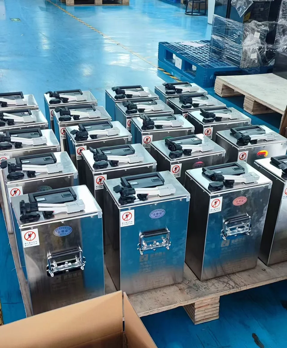
Battery assembly context
DRAWINGS / DOCUMENTS
Drawings and technical documents.
Request the documents relevant to your configuration. Share your installation drawing or brief so the engineering discussion starts with the right constraints.
Use a technical inquiry to define which drawings and datasheets your project needs.
Request a Drawing ↗Project questions
How should a robot's duty cycle be described?
Include travel, standby, task operation and charging. Share peak events and overlapping loads as well as the desired operating duration.
Does this platform include a confirmed host protocol?
No protocol is assumed. Provide the host-controller interface and required battery information so communication and integration can be evaluated.
Have a product to power?
Bring the application, space and operating brief. Start a technical conversation around your project.