
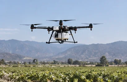
Industrial UAV
Payload duty, propulsion demand and mission continuity.
Discuss this missionCUSTOM BATTERY ENGINEERING / COMMERCIAL UAV
Built around the mission: flight time, weight and peak power.
Every UAV mission sets a different balance between energy, weight and power. We engineer the battery around that balance and the aircraft it has to fit.
For UAV OEMs, UAS platform teams and aircraft integration engineers.
ONE AIRCRAFT. ONE POWER SYSTEM.Pack envelope · weight budget · power interface
Integration close-up · concept image, not a customer case
Choose a short project inquiry or a detailed technical brief.
01 / START WITH THE FLIGHT
Start with the aircraft, payload and the work it must complete. Include the return flight and reserve before choosing capacity.
For UAV OEMs, UAS platform teams and aircraft integration engineers.
Initial propulsion demand
Altitude and payload
Sustained mission energy
Aircraft-dependent load
Energy margin
Reserve and recovery
| Mission requirement | Battery engineering decision |
|---|---|
| Long flight time | Balance usable energy, aircraft weight and the mission reserve. |
| High payload | Review propulsion power demand alongside energy architecture. |
| Takeoff / climb demand | Assess peak current, duration and recovery between load events. |
| Compact aircraft | Compare cell format, pack geometry and available installation space. |
| Rapid turnaround | Evaluate charging and battery swap workflow against mission frequency. |
| Cold / hot operation | Review cell selection and thermal behavior under the intended conditions. |
| Flight controller integration | Define monitoring, telemetry and electrical interface requirements. |
02 / THE WEIGHT–ENERGY TRADE-OFF
More capacity may add energy, but it also adds weight and volume. That extra aircraft load can change the power needed to fly. Capacity alone cannot predict flight time.
Capacity and usable energy
Mass, volume and placement
Mission duration, power and pack geometry
Start with the voltage range required by the aircraft’s motor and ESC. Compare cells and pack configurations against the available space and weight budget.
03 / BEYOND AVERAGE POWER
A high-power UAV battery must be assessed against both continuous demand and brief load events: takeoff, climb, rapid acceleration, payload work, wind compensation and multi-motor transients.
Voltage can fall under load as current flows through the cells and power path. Its behavior depends on the load, state of charge, temperature and system resistance. Evaluate the voltage at the aircraft interface, not only at rest.
Voltage sag can reduce usable energy and propulsion power, and affect the ESC or flight controller. Agree acceptable voltage behavior with the aircraft team; zero sag cannot be promised.
04 / ENGINEERED INTO THE AIRCRAFT
A lightweight drone battery is an integration decision. Pack placement, retention and connector access must work with the aircraft’s weight distribution, vibration environment and maintenance workflow.
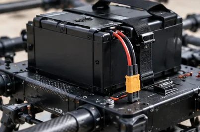
High loads and charging generate heat in cells and connections. Review ambient temperature, altitude, airflow and enclosure limits before choosing a thermal approach.
Plan charging around mission frequency and the facilities available. Faster turnaround must still respect the selected cells’ charging limits.
05 / PART OF THE FLIGHT SYSTEM
The battery works with the aircraft’s ESC, motors, propellers and payload. Your team’s propulsion specification guides battery integration; motor and ESC design remain outside this scope.
Define the voltage, current, temperature, charge estimates and fault information the aircraft needs. Confirm the interface and protocol before including telemetry in the design.
Protection behavior and aircraft fault responses must be reviewed together. Define the response to abnormal conditions and evaluate it during system integration.
06 / FROM REQUIREMENT TO EVIDENCE
Agree the validation plan before production release. Combine representative bench loads with customer aircraft testing where needed, and confirm who will perform flight validation.
| Requirement | Validation question |
|---|---|
| Flight time | Does usable energy support the mission duration and agreed reserve? |
| Peak load | Is battery behavior suitable under the mission peak load and its duration? |
| Voltage stability | Does the electrical system stay within agreed limits through load changes? |
| Thermal | Is temperature behavior acceptable during mission and charging conditions? |
| Mechanical fit | Does the pack integrate securely, with suitable balance and service access? |
| Charging | Does the charging workflow support the required mission turnaround? |
Agreed specification, approved BOM, interface definition, work instructions and quality criteria support the production release. Pilot review and change control help preserve the validated configuration. Production consistency must be checked against project criteria, not assumed from a prototype.
07 / COMMERCIAL & INDUSTRIAL MISSIONS
Each mission changes the balance between flight time, payload and turnaround.
Payload duty, propulsion demand and mission continuity.
Discuss this mission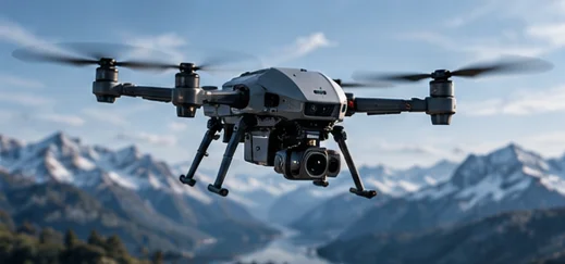
Hover or maneuver demand, reserve and changing site conditions.
Discuss this mission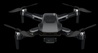
Route duration, aircraft weight and repeatable turnaround.
Discuss this mission08 / SUPPLIED PRODUCT & PROCESS MATERIAL
These supplied product and process materials support the engineering discussion. They do not establish a customer case, flight-validation result, aircraft approval, production rate or approved specification.
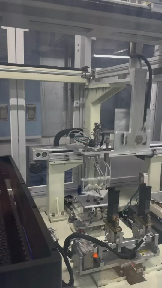
A short, silent view of cell-processing equipment in operation.
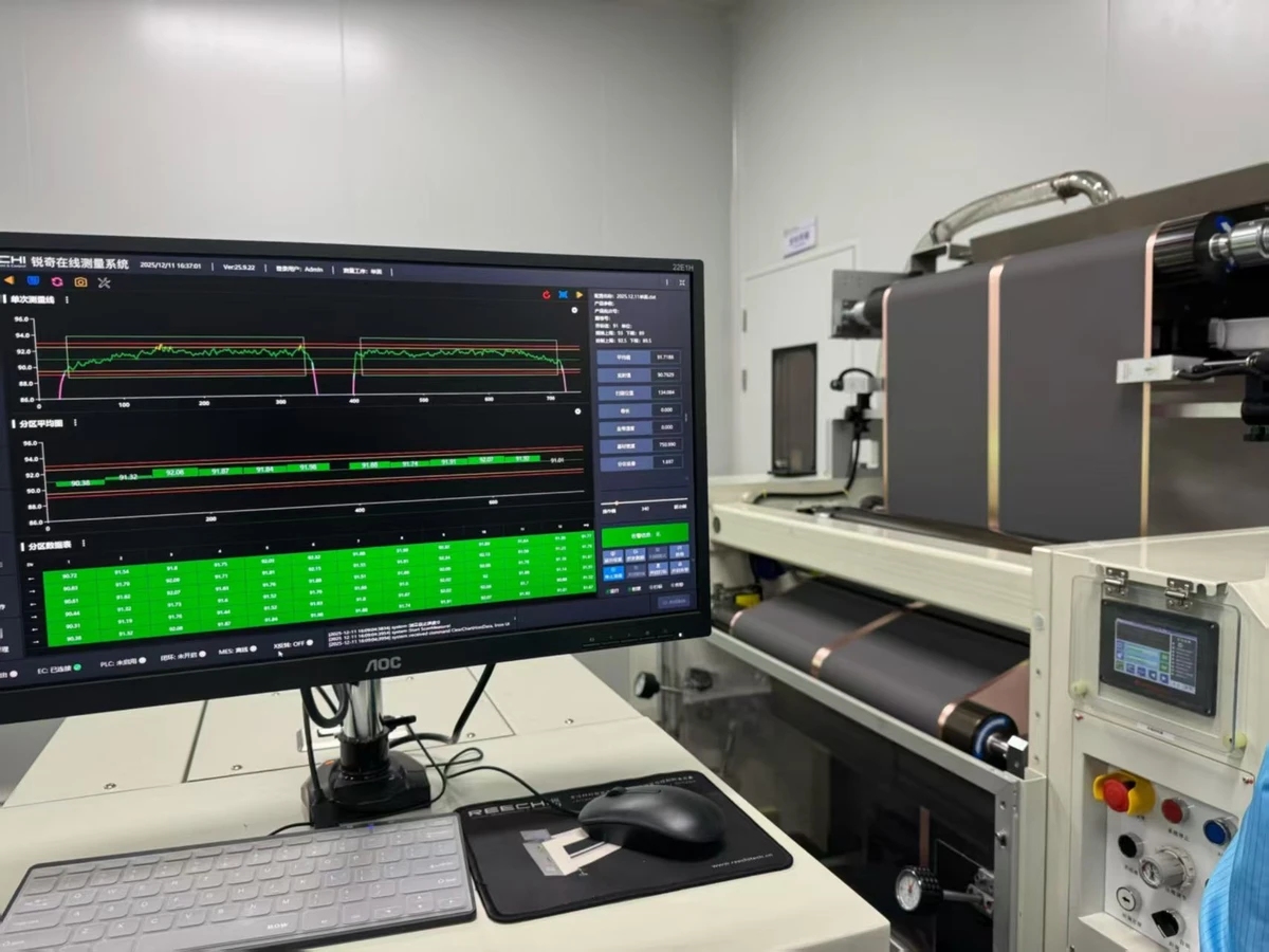
A view of monitoring equipment at a battery workstation.
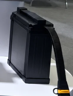
Enclosure detail from the supplied UAV battery display.
09 / YOUR AIRCRAFT, YOUR REQUIREMENTS
Start with what you know. Unknown requirements can be discussed.
TECHNICAL QUESTIONS
Start with the aircraft, payload and mission load profile. Evaluate usable energy, voltage range, continuous and peak current, reserve, weight and available space together. Cell and pack choices then need validation against the aircraft rather than a capacity-only comparison.
More capacity can increase stored energy, but added mass can also increase the power required to fly. The balance depends on propulsion, payload and mission. No flight-time gain can be promised without aircraft-specific evaluation.
Takeoff, climb, maneuver and payload work can create demand above the mission average. Peak magnitude, duration and repetition influence cell choice, configuration, conductors, connectors, protection and thermal evaluation.
Current through the cells and the power path produces a voltage drop. Load, state of charge, temperature and resistance affect the observed voltage. Review behavior under representative loads against ESC, propulsion and host-system requirements.
Envelope, mounting, connector position and cable routing can be evaluated during project definition. Feasibility depends on the selected cells, electrical requirements, mass budget and aircraft integration constraints.
Define the power interface, retention, weight distribution, vibration requirements and monitoring needs. Evaluate battery behavior with customer-supplied propulsion and flight-controller requirements. Protocol support and protection behavior are agreed for the project.
Charging, multiple-pack rotation, swaps and station interfaces can be evaluated against mission frequency and workflow. Charge limits depend on the selected cells, pack and temperature conditions; rapid charging is not assumed to suit every design.
Agree electrical, load, voltage, thermal, mechanical and charging acceptance criteria. Prototype evaluation may combine representative bench loads with customer aircraft and mission testing, followed by revisions before production release.
Share aircraft type, mission, voltage, flight-time target, payload, weight and size limits, load data, connector, charging, environment and expected quantity. The Technical RFQ includes a requirement-file step. Unknown details can be discussed; submitting the page brief only opens that form.
FROM MISSION TO BATTERY SYSTEM
Bring the aircraft brief. Define the battery around the mission, then validate it as part of the system.
Choose a short project inquiry or a detailed technical brief.