
The Battery Is Part of the Machine
Define the available envelope, pack shape, retention, connector location, cable routing, weight distribution and mechanical protection together. Battery placement must support both installation and maintenance.
CUSTOM BATTERY ENGINEERING / AUTONOMOUS EQUIPMENT
Built for long missions, changing loads and demanding environments.
For autonomous and remote equipment, the battery has to fit the machine, support changing loads and stay visible to the control system.
Autonomous equipment system
EQUIPMENT DETAIL / OPERATING MISSION
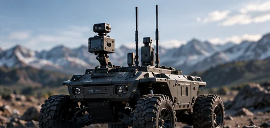
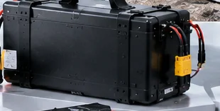
ENCLOSURE DETAIL / BATTERY SYSTEM
Define the power system around the job it must keep doing.
Concept details · not a customer case or matched configuration
Choose a short project inquiry or a detailed technical brief.
For commercial UGV OEMs, inspection platform teams and remote equipment integrators.
01 / THE OPERATING BRIEF
An autonomous platform may wait, travel, work and communicate before returning to charge. Battery design cannot be reduced to voltage and capacity alone: it must account for what the equipment keeps doing when no operator is beside it.
Keep essential systems available
Supply the moving platform
Support the equipment task
Evaluate overlapping demand
Maintain agreed status visibility
Plan the next operating cycle
| Equipment requirement | Battery system decision |
|---|---|
| Long unattended runtime | Usable energy and project-defined reserve |
| Variable motor / actuator loads | Power capability and electrical architecture |
| Outdoor environment | Cell, enclosure, thermal and validation considerations |
| Limited charging access | Charging, battery swap and energy planning |
| Remote status visibility | BMS monitoring and host interface requirements |
| Field service / installation envelope | Pack geometry, connector, mounting and maintenance workflow |
02 / ENERGY THROUGH THE MISSION
Build the energy requirement from time spent in each operating state. Include controllers, sensors and communications alongside travel and mission work; a low-power waiting period still consumes energy.
Travel + task loads over their duty cycles
Standby + sensors + computing + communication
Return energy + operational uncertainty
Average demand informs the energy budget. Peak magnitude, peak duration and simultaneous loads also shape cell selection, connections, protection and thermal evaluation.
03 / FIELD CONDITIONS
Define where the equipment will work and be stored. Those conditions guide cell, enclosure and interface choices; any environmental rating needs validation.
| Environment requirement | Engineering consideration |
|---|---|
| Temperature | Cell behavior, heat paths and charging conditions |
| Dust / moisture target | Enclosure, connector and sealing requirements |
| Vibration / shock / terrain | Mounting, retention, mechanical structure and validation |
| Outdoor service | Inspection access, connector handling and enclosure maintenance |
| Remote installation / storage | Charging access, service intervals, fault visibility and storage conditions |
Define the available envelope, pack shape, retention, connector location, cable routing, weight distribution and mechanical protection together. Battery placement must support both installation and maintenance.
Plan access, removal, inspection and replacement without unnecessary equipment disassembly. Agree pack identification and the information a technician needs to investigate a fault.
Choose charging to match access, uptime and field service. Each approach affects heat, connectors, battery control and the number of packs in use.
Options to review · compatibility must be confirmed.
04 / POWER AND INFORMATION
Battery information can form part of the host equipment requirements. Define which conditions the controller needs to see, how they are communicated and what should happen when an agreed limit is reported.
Agree signals, charge estimates and interface compatibility with the equipment team. This is not live telemetry.
05 / FROM DESIGN TO RELEASE
Build a validation plan for the mission, from battery checks to representative loads and equipment trials. Agree acceptance criteria and test responsibilities, including any external environmental testing.
| Requirement | Validation question |
|---|---|
| Runtime | Does usable energy support the required operating mission? |
| Variable / peak load | Is battery behavior suitable through maximum and overlapping demand? |
| Environment | Are cell and enclosure requirements aligned with operating conditions? |
| Communication | Does battery information integrate correctly with the host controller? |
| Charging | Does the workflow support equipment availability? |
| Mechanical / service | Is the pack securely integrated, accessible and replaceable? |
| Fault handling | Are system responses defined for battery limits and faults? |
Freeze the agreed design, BOM, interfaces and acceptance criteria. Define assembly documentation, pilot review and change control before production release; project outputs depend on the agreed scope.
06 / COMMERCIAL & INDUSTRIAL APPLICATIONS
Travel, sensing and field access each put different demands on the battery.
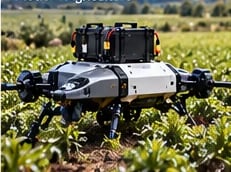
Travel, variable terrain and task loads shape the operating energy brief.
Discuss this equipment brief
Account for sensing, computing and the energy needed to complete the route.
Discuss this equipment brief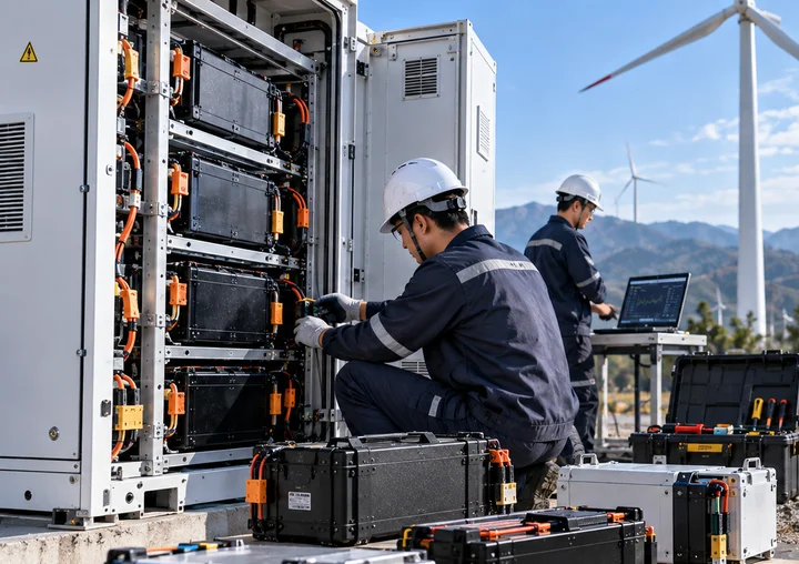
Charging access and field service become part of the system definition.
Discuss this equipment brief07 / SUPPLIED PROCESS EVIDENCE
Supplied workshop and equipment photographs provide process context. They are not evidence of a specific UGV deployment, environmental rating or validation outcome.
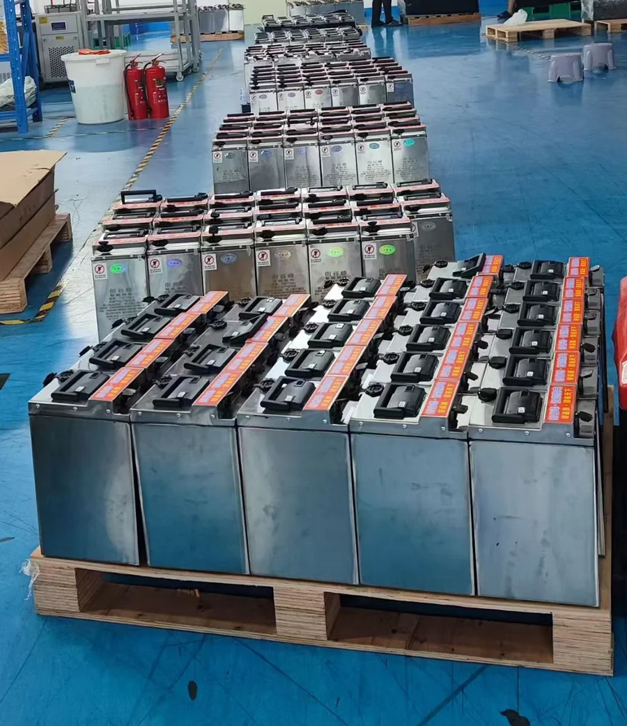
Physical pack format, handling access and assembly consistency belong in the production discussion.
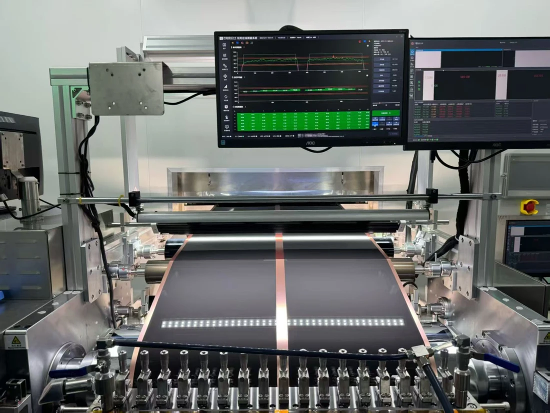
Define the electrical checks and records needed for production.
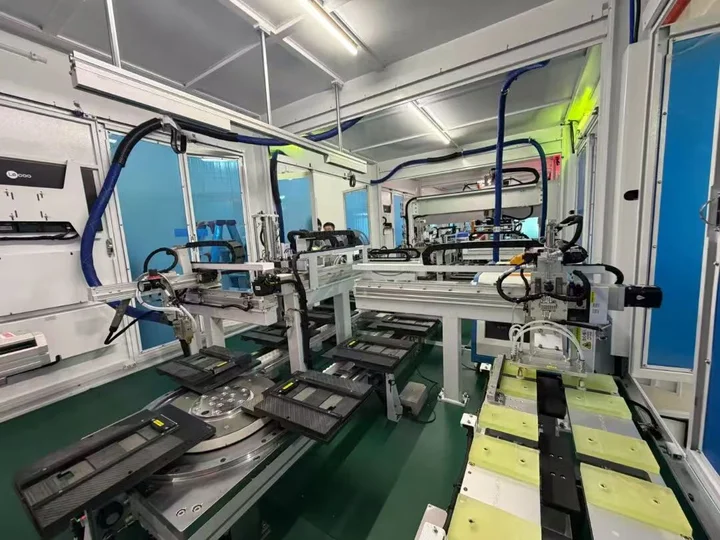
Review how agreed design and quality criteria are carried into production.
08 / START AN ENGINEERING CONVERSATION
Tell us what the equipment does and where it works. You do not need a complete specification to start.
TECHNICAL QUESTIONS
Start with the equipment type, mission, runtime target, voltage, loads, available space and environment. Include charging access, communication, service needs and expected quantity. Uncertain requirements can be reviewed during project definition.
Estimate energy across active work, travel and standby, including sensors, controllers and communication. Compare the mission with usable battery energy and an agreed reserve for return, uncertainty and charging access. Capacity alone does not establish runtime.
Magnitude, duration and overlap matter alongside average demand. Motor startup, actuation and simultaneous loads inform cell choice, electrical paths, protection and thermal evaluation. The equipment load profile is needed before performance can be specified.
Battery status and fault information can be evaluated as host integration requirements. The interface, signals and any SOC or SOH strategy must be agreed for the project; no protocol or remote software capability is assumed.
Define temperature, dust, moisture, vibration, shock and storage conditions. These inform cell, enclosure, connector, mounting and validation decisions. A requested environmental target is not a confirmed rating.
Charging access and equipment availability guide evaluation of fixed, dock, opportunity, field or swap workflows. Compatibility, protection, thermal behavior and service arrangements must be reviewed; every option is not suitable for every project.
Review battery access, removal, connectors, inspection, replacement and identification during mechanical integration. Agree the information needed for field service without assuming a predictive-maintenance or remote-diagnosis platform.
Agree a plan against the operating mission, loads, environment, interfaces, charging and fault response. Evaluation may occur at battery, representative-load and equipment level, with responsibilities and acceptance criteria defined for the project.
Yes. Use Upload Equipment / Battery Requirements to open the attachment step of the existing Technical RFQ. Add the project and contact details required by the form before submitting. The brief on this page only prefills that form.
YOUR EQUIPMENT. YOUR OPERATING MISSION.
Bring the mission, the constraints and the questions. Start with a technical brief for your unmanned equipment battery project.
Choose a short project inquiry or a detailed technical brief.