
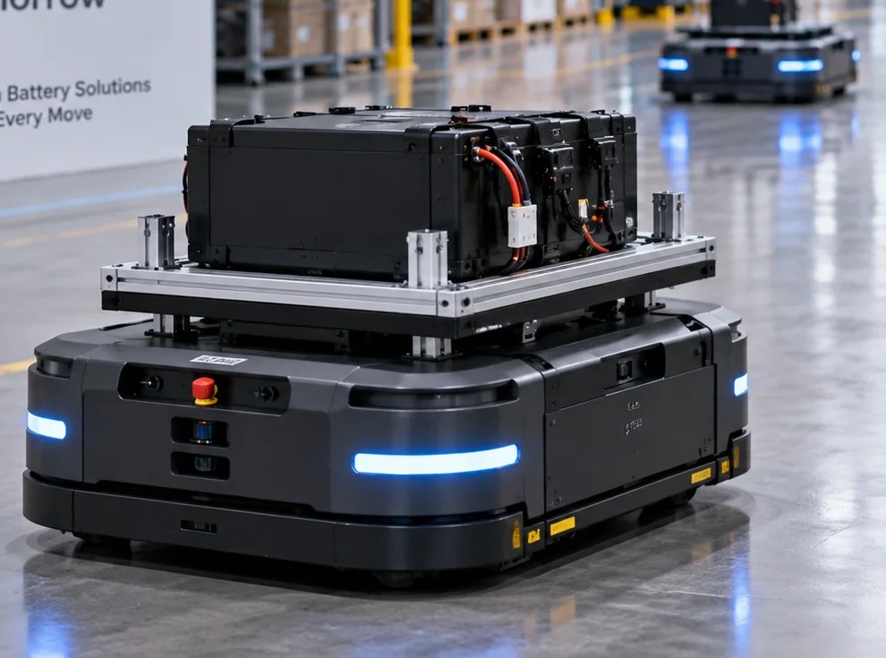
AMR / AGV
Long shifts, fleet charging, host communication and production consistency.
Prepare this robot brief — AMR / AGVAPPLICATION ENGINEERING / ROBOTICS
Built around the way your robot works.
THE BATTERY, IN CONTEXTPower, fit and interfaces begin with the robot.
A robot’s working cycle shapes its battery. We bring runtime, peak loads, charging and controller interfaces into one custom system.
Choose a short project inquiry or a detailed technical brief.
From the first mission profile to robot integration and production planning.
01 / START WITH THE MISSION
A robot accelerates, lifts, pauses, senses and returns to charge. Its working cycle—not a capacity label—defines the battery brief.
| Robot requirement | Battery system decision |
|---|---|
| Long operating shift | Match usable energy and charging windows to the working shift. |
| High motor peaks | Review cells, parallel architecture, conductors and protection against the load profile. |
| Limited chassis space | Balance cell format, enclosure, weight and the installation envelope. |
| Frequent charging | Balance charge acceptance, heat, connector wear and cycle targets. |
| Host controller integration | Define BMS data, communication behavior and fault handling. |
| Demanding environment | Agree temperature, dust, moisture, vibration and validation requirements. |
02 / ENERGY + POWER
Start with the power and time needed for each task. Review usable energy, charging windows, temperature, and space or weight constraints before choosing a capacity target.
Average load and time shape the energy budget. Account for idle periods, auxiliaries, reserve strategy and the energy available under the agreed operating conditions.
Startup, acceleration, lifting, inclines and simultaneous actuators can change the peak demand. Review its magnitude, duration and repetition—not just the average load.
LOAD PROFILE → PACK DESIGN REVIEW
03 / BMS + COMMUNICATION
Agree what the controller needs to know, when it needs to know it, and how the robot should respond when a limit or fault is reported.
Include the required interface in your brief, whether CAN, RS485, SMBus or another protocol. Compatibility, message definitions and firmware scope need confirmation.
04 / FIT + OPERATION
The pack is part of the robot’s mechanical architecture. Define its location alongside the chassis, service access and connections.
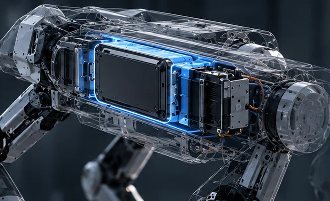
Define temperature, dust, moisture, vibration and connector exposure for the robot’s workplace. Agree the targets and validation plan before assigning any environmental rating.
Choose a charging approach that fits the duty cycle. The options below need review against cell limits, available downtime and the robot’s workflow.
| Strategy to evaluate | What the design must resolve |
|---|---|
| Standard charging | Available downtime, charger compatibility and charge limits. |
| Fast charging | Cell suitability, available power, heat and lifetime trade-offs. |
| Opportunity charging | Short charge windows, mission scheduling and state-of-charge strategy. |
| Dock charging | Alignment, contacts, communication and charge permission. |
| Battery swap | Safe disconnection, handling, retention and connector durability. |
05 / SYSTEM INTEGRATION
Connect the power path, controller information and charging interface into one system design.
POWER PATH
MONITORING + CONTROL
The BMS monitors the pack and coordinates protection; it exchanges agreed data with the robot controller.
CHARGING INTERFACE
Review cell limits, electrical and BMS protection, mechanical protection, heat and charging behavior as one design. Define responses and verification criteria without assuming risk can be eliminated.
06 / PROTOTYPE → ROBOT → PRODUCTION
Bench evaluation is a checkpoint. Representative loads and robot integration help verify the behavior that matters in operation. Test scope, facilities and responsibilities are agreed for each project.
Resolve prototype findings before design freeze. Agree the BOM, interface definitions, work instructions, quality criteria and pilot review. Control later changes to support repeatable builds.
Explore engineering validation and production release| Requirement | Validation question |
|---|---|
| Runtime | Does usable energy meet the agreed mission duration and reserve strategy? |
| Peak load | Does the pack respond to the operating load profile, including repeated peaks? |
| Charging | Does charging fit the intended workflow and agreed operating limits? |
| Communication | Does BMS data integrate correctly with the robot controller? |
| Thermal | Are temperatures and thermal behavior acceptable under representative conditions? |
| Mechanical fit / connector | Are mounting, access, cable routing and connections suitable for operation? |
| Fault handling | Do the battery and robot respond and recover as defined? |
| Application operation | Does the integrated system behave as intended across the duty cycle? |
07 / ROBOTICS APPLICATIONS
Long shifts, fleet charging, host communication and production consistency.
Prepare this robot brief — AMR / AGV
Compact fit, field charging, environmental exposure and mission runtime.
Prepare this robot brief — Inspection robots
Weight, frequent charging, compact packaging and straightforward maintenance.
Prepare this robot brief — Delivery & service robotsApplication concepts · not customer cases.
08 / REAL PROCESS PHOTOGRAPHY
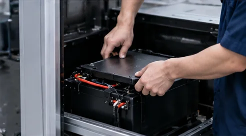
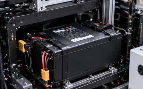
These supplied photographs show battery assemblies, production activity and equipment. They provide process context, not proof of a robotics deployment or a test result.
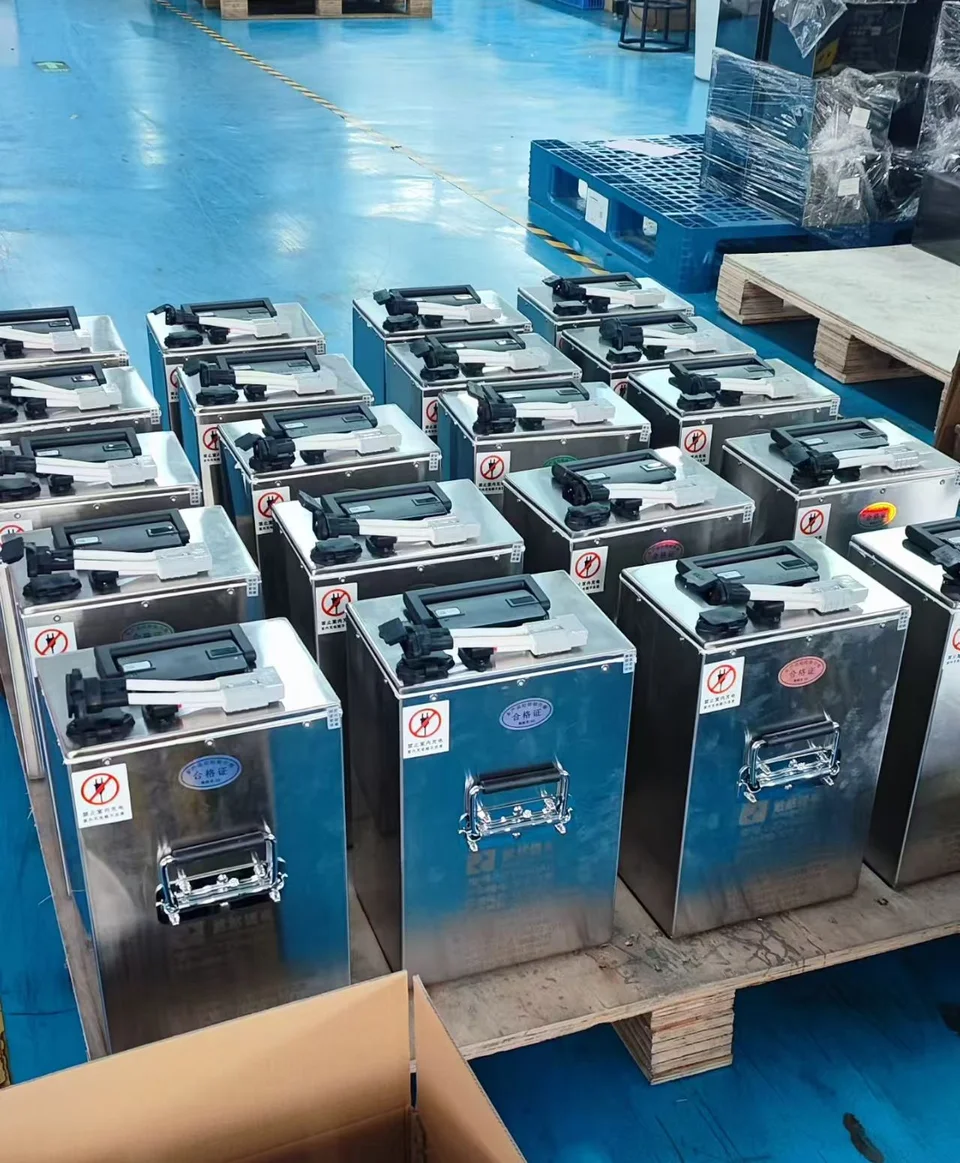
Pack construction and handling provide a starting point for discussing integration with your robot.
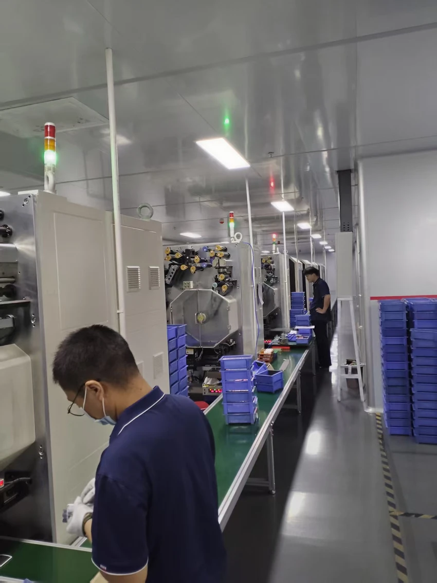
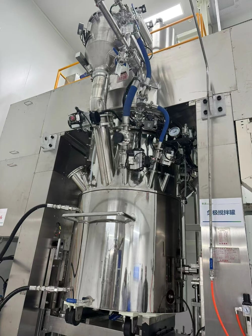
A robotics validation report or customer case will be shown only after source and publication approval.
A standard battery may be appropriate when its defined dimensions, electrical architecture and interfaces satisfy the complete robot brief.
Consider a custom system when the robot needs a different fit, load response, charging approach or interface.
Custom is not automatically the better choice. Review suitability, development scope, cost and supply considerations first.
09 / YOUR ROBOTICS PROJECT
Start with what you know about the robot and its working cycle. You can review the details in the Technical RFQ.
Add dimensions, weight, peak load if known, expected quantity and any drawings. Leave uncertain details for discussion.
Share the robot type, duty cycle, voltage, runtime target, peak load if known, available space, weight target, charging workflow, communication and environment. Add expected quantity and drawings where available. Mark unknowns for discussion.
Start with the power and duration of each operating state, including idle loads and charging opportunities. Review usable energy, reserve strategy, temperature and size or weight constraints. Capacity is selected against that brief and then validated under representative operation.
Startup, acceleration, lifting and concurrent actuators may create peaks. Their magnitude, duration and repetition influence cell selection, pack architecture, conductors, protection, connectors and thermal evaluation.
Pack geometry, mounting and connector position can be evaluated against the robot envelope. Feasibility depends on the electrical requirements, cell options, clearances, cooling and service access. A concept drawing is not an approved production design.
Communication requirements are defined during scoping. Specify the required signals, protocol, message map, timing and fault behavior. CAN, RS485, SMBus or another interface requires project-specific confirmation; support is not assumed.
Standard, fast, opportunity, dock charging and battery swap can be evaluated as operating strategies. Suitability depends on cells, charger compatibility, thermal conditions, connections, cycle requirements and the robot workflow.
Agree questions for runtime, peak load, charging, BMS data, thermal behavior, mechanical fit, connectors and fault handling. Use a prototype with representative loads or the robot system. Facilities, responsibilities, standards and acceptance criteria are agreed for the project.
Yes. Continue to the Technical RFQ and its file step to add a permitted attachment. The form shows the current file type and size limits. Uploading requirements does not establish feasibility or approve a specification.
FROM ROBOT REQUIREMENTS TO A BATTERY BRIEF
Bring the mission, the constraints and the questions. Define the battery system around the robot.
Choose a short project inquiry or a detailed technical brief.